Training High-Technology Equipment
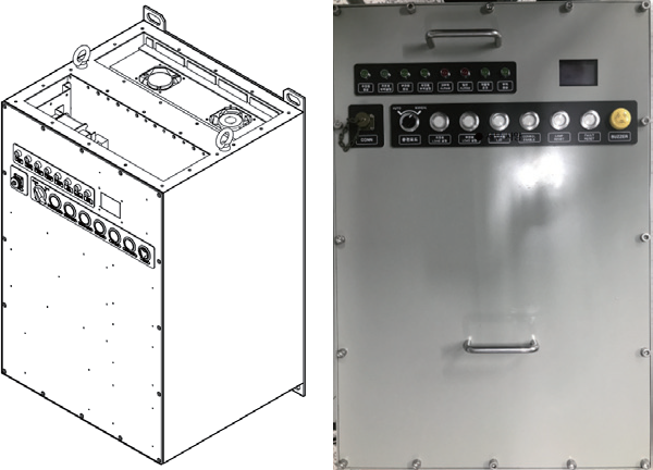
SABT
Static Automatic Bus Tranfer
The SABT monitors the main power voltage, which reduces the load to the power source if the main power source falls below the cut-off threshold setting.
Features
- Faulty, current power status OLED display is possible
- Setting voltage remotely, Check various error information, etc (Existing equipment is changed only when the DIP switch is adjusted within the PCB)
- Can check and set up all N devices on the main PC
- Fast and scalable communication speed at 250Kbps based on CAN communication
- Excellent cooling performance and durability with integrated heater sink
differentiation
| category | Existing Products | Developed products |
|---|---|---|
|
Status presentation
|
|
|
|
Remote control
|
|
|
|
Communication
|
|
|
|
Maintenance and repair
|
|
|
Detailed Specifications
| Characteristics | Specifications | |
|---|---|---|
|
Electrical Characteristics
|
||
|
Input Power
|
Voltage Normal | 450VAC / 3-Phase, 120VAC /3-Phase |
| Voltage Range | 8 Button Keys | |
| Frequency | 55Hz to 63Hz | |
|
Output Power
|
Rating | 450VAC / 3-Phase, 120VAC /3-Phase |
|
Load Capacity
|
50A to 400A | |
|
Storage Temperature
|
-40 to 70℃ | |
|
Operating Temperature Range
|
0 to 50℃ | |
|
SCR Spec
|
1.6KV / 600A(average) | |
|
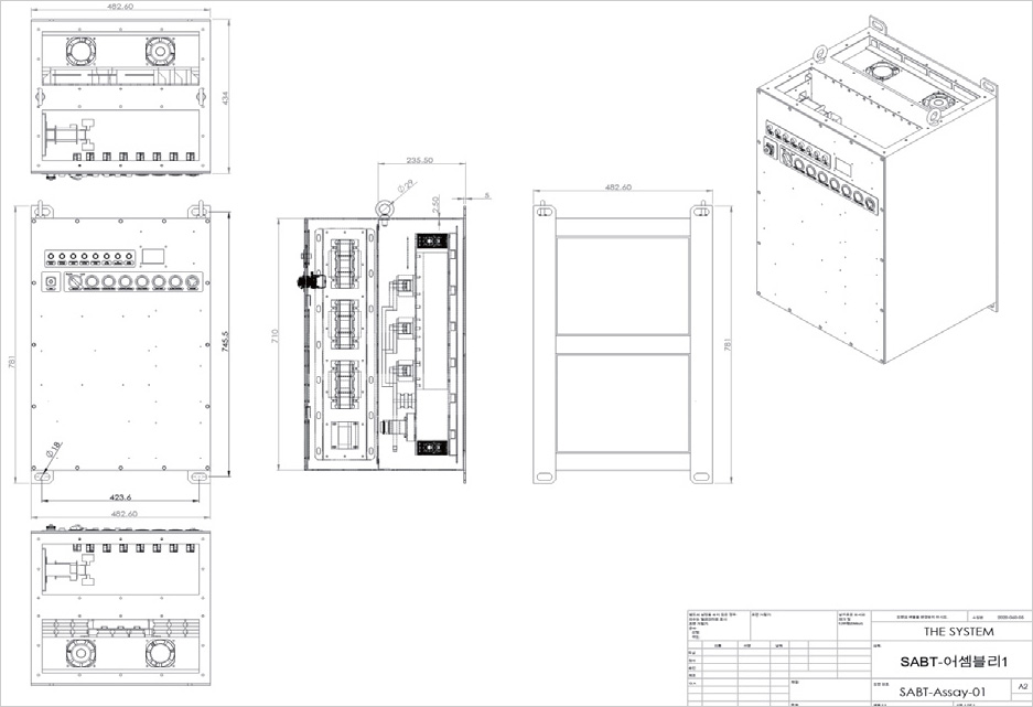
Dimension
|
482(W) X 434(D) X 781(H)mm | |
|
Load Capacity
|
600A | |
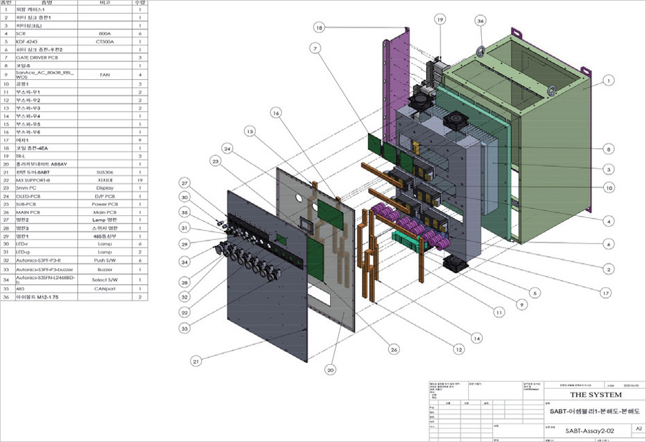
System Configuration Chart
Performance Test Results
Low-voltage & high-voltage cutoff test
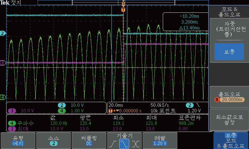
Switch from auxiliary power to main power
- The main power is returned to the effective range from the high voltage state, reducing the main power back to within 1 msec of the load power

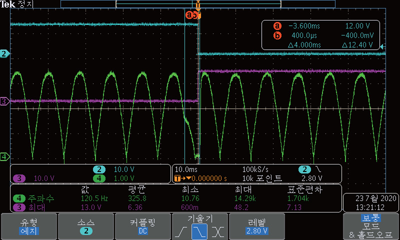
Switch from main to auxiliary power
- 1 msec cut to auxiliary power if the main power gradually changes to high voltage and deviates from its effective range
Cut to main power open circuit
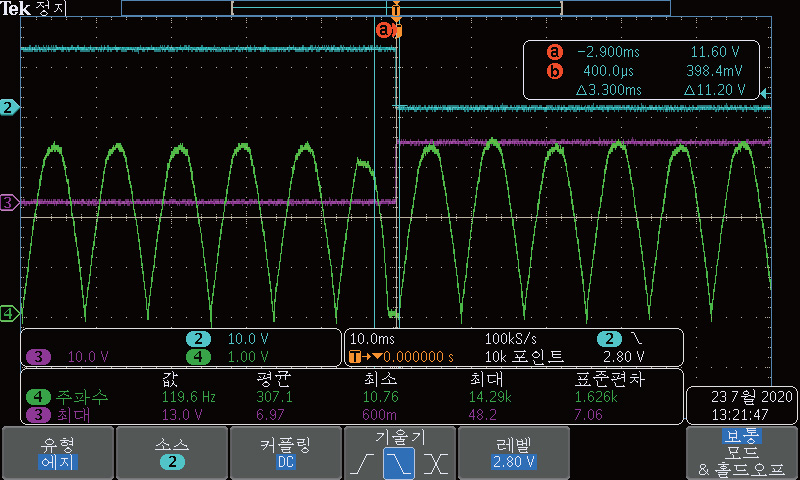
The main power is disconnected and forced out of the auxiliary power
- While the main power source is applied to the load power source, the power source is forcibly cut off from the outside, and the auxiliary power source is cut off within 3.3 msec to maintain the load power source